| FingerTec® Application Solution - Long Range Card Solution for Car Access System |
||||||||||
| ( by Henry Pang, Product Development Manager ) |
||||||||||
| FingerTec® terminals are now compatible with long-range card system, where communication between the long-range station and FingerTec® terminals is accomplished via Wiegand 26-bit input and output. Implementation of the system using FingerTec® terminals require no meddling with the card station and the cards, as all information is collected into the FingerTec® terminals before it is downloaded into TCMS V2 software for reports and analysis. | ||||||||||
The Introduction |
||||||||||
Car access management is a very basic security system applies in condominiums, apartments, housing estate and etc. The main objective is to prevent unauthorised individuals to drive into the boundary without gaining permission from the authority. Barriers are installed at entrances and exits as checkpoints for incoming and outgoing vehicles. Residents shall prove that he/she is a resident before he/she can drive into or leave the area. Visitors are only allowed restricted access and parking space, and details of the visitors are gathered by patrolling guards before permission is given. To simplify the system, RFID cards system was introduced a while back where tenants are issued with RFID cards. To gain entry or exit, tenants are required to wave the RFID card to the sensor at the barrier for verification. The introduction of RFID card spells convenience to a lot of users because of its user-friendliness and to administration too because the system collects user information, card information, time of coming and going into a computer. However, there are some flaws in the operations such as tenants left cards at home therefore, vehicle couldn’t exit, lost of cards, using of cards by unauthorised individuals. The long range RFID card system was introduced to overcome the hiccups in the card system operation. The new system requires an access card to be installed inside the tenants’ vehicles, operated by an internal battery to emit signal. When a tenant’s vehicle approaching the barrier, the sensor detects the signal for controller to read, verify and open the barrier. The new system manages to solve a few issues mentioned above including sharing of cards, forgotten cards and lost cards. |
||||||||||
| Deployment of FingerTec® in Car Access Management | ||||||||||
| FingerTec® terminals are not equipped with any long-range readers but the FingerTec® terminals are equipped with Wiegand input and output features which can work with long-range reader. The main advantage of using FingerTec® in the system is the powerful TCMS V2 software to control access, to prepare reports and analysis. | ||||||||||
|
||||||||||
| Technology Characteristics of FingerTec Solution | ||||||||||
| The Hardware – The Overview | ||||||||||
|
||||||||||
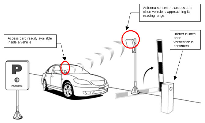
The management will only install access cards into vehicles of registered tenants; therefore, by default the access card will be readily available inside a vehicle. The common access card is an RFID card (radio frequency identification) in greater frequency range. When a vehicle is approaching the barrier, the antenna will sense the access card. The antenna then reads the information from the access card and sends the information to the main controller for verification. The barrier only lifts once the verification is successful. The same operation applies to both entry and exit barriers. |
||||||||||
|
||||||||||
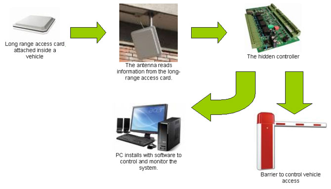
| The controller is installed away from the public view to protect it from vandalism. The controller functions include: | ||||||||||
|
||||||||||
| The Hardware – Enhanced by FingerTec® Kadex | ||||||||||
|
||||||||||
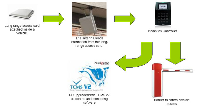
| Instead of using a controller, the system could replace it with FingerTec® Kadex, as Kadex has the same functions as a controller. TCMS V2 must be installed into a PC to work with Kadex. | ||||||||||
| Use TCMS V2 to do the followings: | ||||||||||
|
||||||||||
| The Connection between Antenna and Kadex | ||||||||||
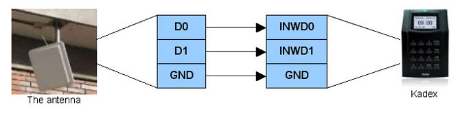
The system with Kadex operates similarly like the system that uses controller. Vehicle approaches the reading distance of antenna. Antenna reads and captures card information from the access card inside the vehicle. The card information will be sent to Kadex for verification. The connection between antenna and Kadex is established using Wiegand 26-bit. The antenna captures and sends card information from its 26-bits Wiegand output port and the information is transferred into Wiegand 26-bits input port of Kadex. |
||||||||||
| The connection diagram is as below: | ||||||||||
|
||||||||||
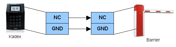
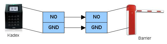
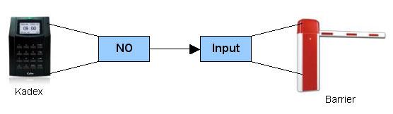
| The Connection between Barrier and Kadex | ||||||||||
| Kadex terminal only emits signal to the barrier after a successful verification. If the card information is invalid or incomplete, Kadex will fail the verification process and it will not emit any signal to the barrier. Kadex controls the barrier either by EM output (DC12V) or relay output (dry contact). The type of output very much dependant upon the barrier input. | ||||||||||
|
||||||||||
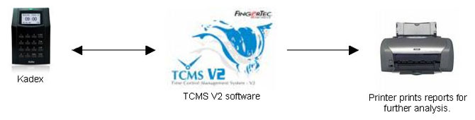
| The Connection between TCMS V2 and Kadex | ||||||||||
|
||||||||||
| The connection between Kadex and TCMS V2 software can be with cable (TCP/IP, RS232, or RS485) or without cable (USB flash disk). As mentioned earlier, the TCMS V2 is important for management of users, cards, vehicles, and records. | ||||||||||
| About Wiegand Interface | ||||||||||
The Wiegand interface is a wiring standard which arose from the popularity of Wiegand effect card readers in the 1980s. It is commonly used to connect a card swipe mechanism to the rest of an electronic entry system. The sensor in such a system is often a Wiegand wire based on the Wiegand effect discovered by John R. Wiegand. A Wiegand-compatible reader is normally connected to a Wiegand-compatible security panel.
The Wiegand interface uses three wires, one of which is a common ground and two of which are data transmission wires usually called DATA0 and DATA1 but sometimes also labeled Data High and Data Low. When no data is being sent both DATA0 and DATA1 are at the high voltage. When a 0 is sent the Data Low wire (also called DATA0) is at a low voltage while the Data High wire stays at a high voltage. When a 1 is sent Data High is at the low voltage while Data Low stays at the high voltage. The high voltage level is usually +5VDC to accommodate for long cable runs (most reader manufacturers publish a maximum of 500 feet) from the door readers to the associated access control panel typically located in a secure closet. The communications protocol used on a Wiegand interface is known as the Wiegand protocol. The original Wiegand format had one 1 parity bit, 8 bits of facility code, 16 bits of ID code, and a trailing parity bit for a total of 26 bits. The first parity bit is calculated from the first 12 bits of the code and the trailing parity bit from the last 12 bits. However many inconsistent implementations and extensions to the basic format exist. An advantage of the Wiegand signaling format is that it allows very long cable runs, far longer than other interface standards of its day allowed. |
||||||||||
| Cited from Wiegand interface. (2009, October 6). In Wikipedia, The Free Encyclopedia. Retrieved 05:34, October 28, 2009, from http://en.wikipedia.org/w/index.php?title=Wiegand_interface&oldid=318212237 | ||||||||||